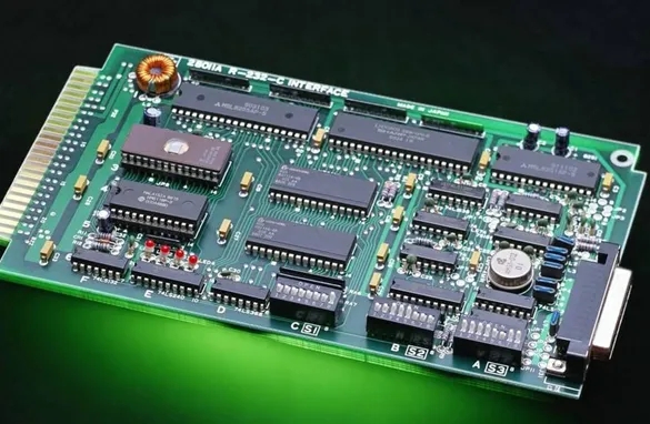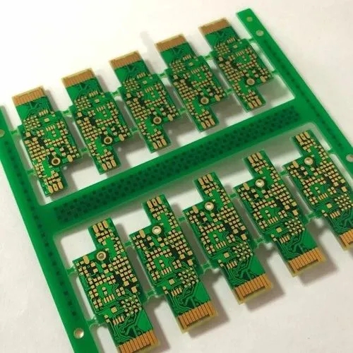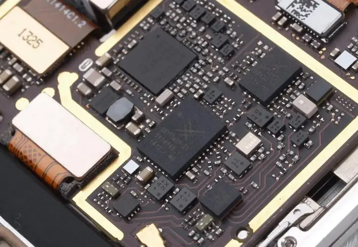
What are the main assembly failure mechanisms of the circuit board?
The failure mechanism of the circuit board falls into three groups:
? Failure caused by heat - plating through hole failure is the most typICal example in this regard
? Mechanical failure
? ChEMIcal failure - the growth of dendritic metal structure is the most typical example
The circuit board will be subject to various thermal stresses, which may be prolonged exposure to high temperatures or repeated temperature cycles, which may lead to circuit board failure. The most important sources of thermal stress are:
? Thermal shock and thermal cycle in PCB manufacturing: thermal shock is generally defined as temperature rise and fall faster than? 30 ℃/s, but it still includes any fast rise and fall rate state. The temperature difference plays an important role, such as solder stop polymerization and tin spraying.
? Thermal shock and cycle in PCB assembly: for example, glue polymerization, reflow, wave soldering, and heavy industry use of iron, hot air treatment, molten solder bath tin, etc

? The ambient thermal cycle in operation, such as the temperature difference from indoor to outdoor, or the temperature difference between the ground and the atmOSPhere, may also be the heat loss of high power electronIC parts in the product shell
The main circuit board failure mechanism accelerated by these thermal stresses is the rupture of electroplated through-hole and the peeling of the base material. Plated through-hole is the most vulnerable part of the circuit board to thermal cycling, and also the most frequent location that causes failures in the operation of the circuit board. The plated through hole includes a hole for installing parts and an electrical connection hole.
Most organic resin substrates are non isotropic and have high coefficient of expansion (CTE) above the glass transition temperature Tg, especially in the through hole thickness (Z) direction. Because the temperature exceeds Tg, the expansion coefficient climbs significantly, and more thermal cycles will lead to greater strain in the Z direction, especially at the plated through-hole location. Plated through-hole function is SIMilar to that of rivet, which will hinder expansion behavior, but the copper hole wall may crack under stress, resulting in electrical failure. The following figure helps to increase the relevant strain on the hole wall due to excessive temperature, and the failure may occur in a single cycle or in a progressive aging fracture mode.
For the repeated thermal shock test of high aspect ratio through-hole, from room temperature to circuit board manufacturing (such as tin spraying), assembly reflow temperature (220-250 ° C), and reflow, wave soldering, rework, etc., after nearly ten or less thermal cycles, failure problems are often heard.
From a physical point of view, the number of thermal cycles to failure will be affected by the strain imposed by the cycle and the anti-aging ability of copper, which are all controlLED by some environmental, material and manufacturing parameters. Low cycle metal aging, in which most strains are plastic strains. When using high cycle aging test, this relationship will obviously underestimate the service life of repeated thermal cycles in operation.
Up to now, the simulation of these failure modes can only help to screen the quality of products, and cannot fully present the status of actual products. Therefore, the selected test methods should match the actual product requirements to avoid miscalculation.
The Circuit board manufacturer and circuit board designer explain to you the main assembly failure mechanisms of the circuit board?
然后
联系
电话热线
13410863085Q Q

微信

- 邮箱


