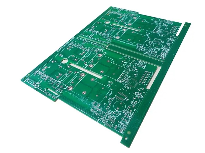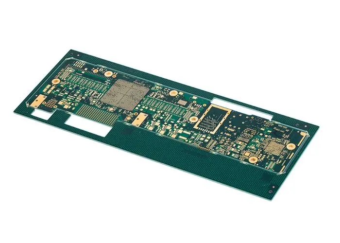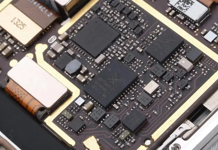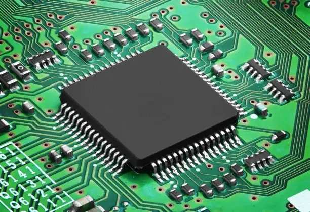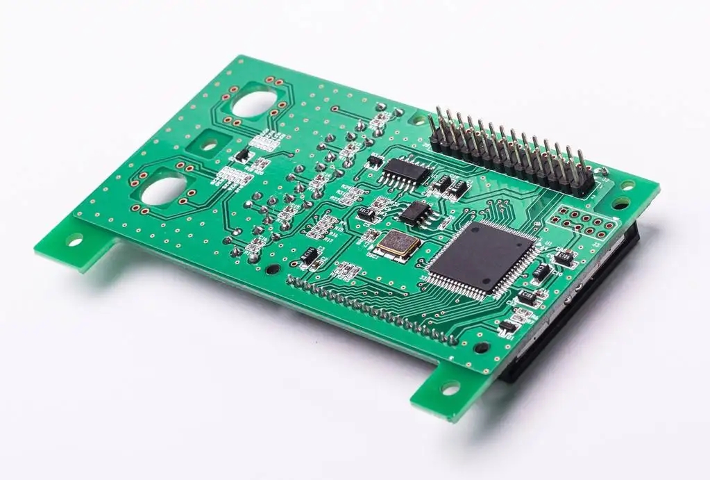
All common techniques for circuit board maintenance are disclosed
circuit board manufacturing, circuit board design and PCBA processing manufacturers explain common techniques for circuit board maintenance
Since most modern circuit boards do not have offICial schematic diagrams, and more and more chips with programs are used, engineers are bound to face challenges in all aspects. Through a large number of practices, it has been proved that there are still ways to escape these challenges. I will share my experience of maintenance over the years with the majority of electronic enthusiasts.
1. Appearance inspection method
That is, through the old method of looking, asking, SMElling and cutting, observe whether there is a burnt place on the circuit board, whether there is a broken place in the copper coating, whether there is a peculiar smell on the circuit board, whether there is a place with poor welding, and whether there is mildew and blackness on the interface and gold finger. Ask the customer about the fault phenomenon and the process of fault occurrence, and often focus on some parts of the fault. Some problems can often be found through the above processing.
2. Pass kill method
That is to say, all components shall be tested once, and the defective components shall be replaced to achieve the purpose of repair. If the components cannot be detected by the instrument are encountered, the replacement method shall be adopted, that is, new components shall be used to replace them regardless of whether they are damaged, so as to finally ensure that all components on the board are good and achieve the purpose of repair. This method is SIMple and effective, easy to use, and does not require high technical level of engineers, but requires a high degree of care and responsibility during operation, otherwise, some devices are not clearly recorded when they are removed, and the wrong installation and reverse installation may easily lead to maintenance failure. In addition, this method is powerless to solve the problems such as through hole blockage, copper coating fracture, and improper potentiometer adjustment. This method cannot be used when encountering chips with programs and data.
3. Comparison method
The comparison method is one of the most commonly used methods for maintenance of circuit boards without drawings, which has been proved to be very effective in practice. The purpose of finding faults is achieved by comparing the status of good boards with that of good boards. Abnormalities are found by comparing the curves of each node of two boards. However, many times we do not have a good board to compare, but this does not mean that we cannot use this method. For example, we can find circuits with the same properties in the circuit board. For example, a board has three identical interfaces, and these three interfaces have the same circuit. Then we can use the mutual comparison curve between the three identical interfaces to judge the problem. When we cannot find the situations mentioned above, we can still find the circuits with common properties, for example, the buses in the circuits usually have the same curve. Sometimes we cannot judge whether an IC is damaged. We may also compare the curve with a good IC by scanning the curve. In short, we need to use our brains to maximize the contrast method. The curve scanning method is really useful in practice, but some beginners do not understand its working principle, and the instrument has no practical value. So I have seen many companies in the same industry basically do not use the circuit board maintenance tester, and cried out. Of course, merchants are suspected of exaggerating this function. In fact, when scanning COMS process ICs, the curves of each scan are different, which leads to the situation that cannot be judged. This is due to the high impedance of CMOS and the lack of discharge channels after charging the inter junction capacitors. Therefore, rich experience is required to judge CMOS integrated circuits. Finally, it should be added that the curve scanning method is to scan the peripheral devices. If the scanning is an integrated circuit, it is to scan the components connected to the pins inside the integrated circuit. 90% of the damage to the integrated circuit is caused by the peripheral devices. However, in case of damage to non peripheral devices, the problem cannot be found when scanning the curve, and the device will have problems when working.
4. State method
The state method is to check the normal working state of each component. If the working state of a component does not conform to the normal state, there is a problem with the component or its affected components. For example, when checking the CPU, we will check whether the crystal oscillator works normally and whether the reset signal is normal. Whether the input and output logic of the NAND gate is correct or not is used to judge whether the device is normal. When using this method, the input is often forced to drive signals. For example, a signal generator is used to give a signal to the input end of the operational amplifier, and an oscilloscope is used to measure the amplitude and distortion of its output signal to judge the operational amplifier. The input level of the logic gate circuit is forced to be pushed up or pulLED down, and the output level is tested to see whether it conforms to the logic of the chip, so as to judge whether the chip is good or bad.
The state method is the most accurate one among all maintenance methods, and its operation difficulty is beyond the grasp of ordinary engineers, which requires rich theoretical knowledge and practical experience. To meet the state requirements, engineers must do everything possible. This method is superior to the curve scanning method in circuit testing, and problems can be found in both peripheral circuits and non peripheral circuits of IC.
5. Substitution method
Replace all ICs with new ones until they are repaired. Nowadays, ICs are getting cheaper and cheaper. 74 series and 4000 series chips are less than 1 yuan per chip. Instead of checking problems one by one, it is better to replace them all. I personally feel that this method is a helpless move, and its shortcomings are also obvious. Its effect should be lower than the pass kill method, which at least needs to judge the components. After a long period of accumulation, I will have some experience on some circuit boards. The repair rate of this method depends entirely on luck rather than effort. Even if it is really repaired, I do not know where the fault is. However, this method still has its merits. If a certain circuit board or electronic device can be used to verify whether it is normal on the spot, we can replace the IC piece by piece. When the fault disappears, it can be proved that the one just replaced is broken. If it is an IC in line package, it is recommended that you install an IC seat immediately after removal. After all, it is only a few cents. Another fatal problem with this method is that you must ensure that the IC you bought is good. If you accidentally encounter a bad IC when purchasing, it will not only fail to repair, but also expand the fault and increase the difficulty of repair.
6. Grounding circuit method
The circuit building method is to make a circuit by hand, and the circuit can work after installing the missing integrated circuit, so as to verify the quality of the tested integrated circuit. For example, in order to judge whether a 555 integrated circuit is good or bad, we can build a time base oscillation circuit made of 555 circuit, and then place the tested integrated circuit in the circuit. If the circuit works normally, it is proved that 555 is OK, and vice versa.
The accuracy of this method can reach 100%, but it is difficult to build a set of circuits for all ICs with various types and complex packaging.
7. Principle analysis method
This method is to analyze the working principle of a board. For engineers, some boards, such as switching power supply, can know their working principles and details without drawings. For engineers, things that know their schematic diagrams are extremely simple to maintain. However, for some relatively complex and rare equipment, there is no ready-made schematic reference to reverse engineer them manually and draw schematic diagrams. With this schematic diagram, it can be said that they are invincible to repair.
This method can only be completed with great patience and careful working attitude of engineers. One effort can benefit permanently, but whether this method is really adopted depends on the value and quantity of maintenance and the difficulty of doing this work. The circuit board manufacturers, circuit board designers and PCBA manufacturers explain the common techniques for circuit board maintenance.
然后
联系
电话热线
13410863085Q Q

微信

- 邮箱


