design Method for Signal Problem of High Speed PCB Board
In high speed PCB board design, signal integrity issues have more and more obvious impact on circuit design reliability In order to solve the problem of signal integrity, design engineers put more time and effort into the constraint definition phase of circuit board design In the early stage of the design process, using design oriented signal analysis tools, running multiple analogies, and carefully planning the circuit board topology can formulate comprehensive design constraints on electrICal and physical characteristics to avoid electromagnetic interference and other related problems The current typical design environment is mostly oriented to the later stage of design, mainly considering the circuit board drawings Design tool providers are now addressing these new design challenges However, design engineers need a new method to solve the increasingly prominent high-speed design problems in design. Design engineers can solve the problems early in the design process
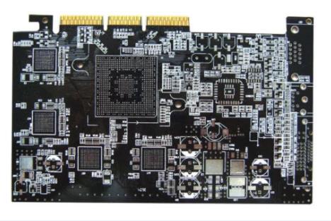
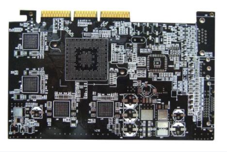
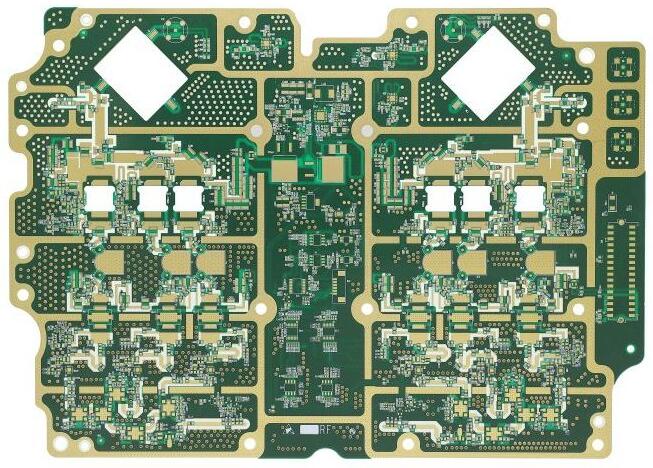
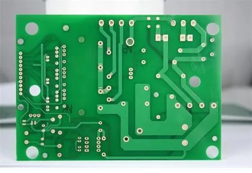
PCB board

Tighter tool integration
To identify and resolve these high speed signal problems without releasing on expensive and time consuming board testing steps, it is essential to conduct extensive signal analysis before circuit board design When design engineers find these problems, they can ensure the success of circuit design by changing the routing and circuit layer distribution, define the routing topology of clock lines, and select components at a specific speed However, the previous signal integrity analysis tools were very limited, either not easy to use or unable to analyze the entire design Therefore, design engineers can only rely on experience to determine the key circuit networks that need attention, or rely on comprehensive signal integrity analysis tools for analysis Design tools began to open up Xintiandi and develop effective analysis tools for high-speed design problems Take the signal integrity analysis tool provided by Innoveda as an example The company's HyperLynx toolset is easy to use and can provide powerful signal integrity analysis functions before and after drawing circuit boards One of its outstanding features is a very user-friendly interface, which enables design engineers to quickly analyze the "possible scenarios" they envision, and experiment with terminal topology and other problems to quickly find solutions that meet the efficiency and reliability. It is suitable for engineers dealing with highly complex circuit boards and systems, Innoveda's XTK signal integrity verification toolset and ePlanner signal integrity planning environment provide advanced algorithms and some verified verifications, high-speed scanning and lossy lines, Monte Carlo methods, and signal integrity analysis algorithms for ultra-high speed signal integrity analysis functions (including topology analysis) In the past, design engineers had to choose between Hyperlynx and XTK Not long ago, Innoveda realized the connection between the two key signal integrity analysis tools. By combining the two tools, they can be used in one design, which can effectively shorten the design cycle Typically, HyperLynx was originally a tool for high-speed PCB signal analysis, while XTK and ePlanner were used for more complex topology analysis and constraint generation
Enhanced wiring capabilities
After determining the routing rules, design engineers turn to physical realization of design Common PCB drawing tools provide a comprehensive component selection function, the ability to set the circuit board layer, assign constraint rules, and manage the placement of all components on the board Good tools must be easy to use, automatically manage all design constraints, and make the final circuit Board Design But this is not enough in the high-speed design environment, and PCB drawing tools must provide a more comprehensive solution Nowadays, some designs are usually very complex and require short development time Design engineers no longer use the past manual drawing methods, otherwise, it is time-consuming and error prone In order to maximize productivity and solve a large number of signal analysis problems, design engineers need a tool that enables them to perform routing in batch processing mode and interactive pipelines power PCB 5. The 0 released by Innoveda meets this design requirement This shape and rule based board design system includes the BlazeRouter HSD (High Speed Design), a high-speed design option that allows automatic routing based on high-speed constraints, including/length, matching length, and differential pair (differential paIR) Such constraints can be placed anywhere in the rule system, and BlazeRouter HSD can automatically implement the design according to these rules With this pipeline, design engineers can set and protect the topology of key circuits to ensure that key signals are connected in the correct order
The tool also adds an interactive routing editor for design engineers familiar with manual routing, and provides extensive special support for networks generated by constraints This new Fast Interactive Route Editor (FIRE) features multiple Design Rule Checking (DRC) modes and new route editing capabilities. Design engineers can automatically add "Z" jacks, find differential pairs, and monitor track length or design according to specific constraint rules With this conduit, design engineers can more easily implement dense wiring design and achieve higher wiring density on fewer circuit board layers In addition, the tool provides graphic echo function for design engineers to demonstrate the impact of routing on other networks on the board In the past, it was difficult for design engineers to know how changes in critical networks would affect the rest of the design BlazeRouter HSD represents these previously difficult effects with graphical pipes, and different colors and brightness represent different effects This can help design engineers understand the possible impact of each routing
Build a complete design approach
These tools represent a major advance in addressing the high-speed issues that are prevalent in circuit board design today. However, more functions must be added to the design tools to adapt to the rapidly increasing clock speed and complexity in circuit board design. In particular, a comprehensive design method is needed to replace today's multipoint design tools What is the design process of the new method? To solve the high-speed problem in the critical path, new functions must be added in the early design definition stage of the process In order to achieve this goal, the new method must have strong analogy and analysis capabilities At the same time, you must be able to understand the key data related to circuit board design, especially the information about component availability and cost Ideally, design engineers can cooperate throughout the company through the design platform. Design engineers can not only exchange design ideas among design engineers, but also communicate with other departments such as procurement and production through the network At the same time, the design of high-speed circuit board depends on constraint generation method to a large extent At present, design engineers input electronIC design data and design constraints into circuit board drawing software to achieve circuit design. However, due to the increasing complexity of signal integrity and circuit board design, this problem is more complex To solve the problem of signal integrity on these high-speed and complex circuit boards, they must make analogy and comprehensive design before drawing circuit boards This puts forward new requirements for the design environment. From electrical characteristics to manufacturing process, design engineers must formulate constraints On an ideal design platform, design engineers can not only formulate power characteristic rules, EMI or crosstalk for parameters such as track length, but also set component placement rules, height constraints, and rotation angles for component spacing
To quickly generate such constraints, the design environment must have strong topological analysis and "what if" analysis capabilities The design engineer is allowed to design and compare the network topology in the form of circuit diagram, and the signal integrity analysis engine is allowed to change the topology parameters in multiple analogies, and then study various termination scheMES, align them with delay constraints, circuit layer options and track spacing, and minimize signal integrity This function should also be closely coupLED with component placement and associated with planning functions, so that design engineers can define initial component placement and understand the effectiveness of routing strategies In conclusion, the new design environment must provide strong constraint management capabilities so that design engineers can organize and manage large amounts of information Not only that, but this new high-speed design method must also provide verification capability at the later stage of the development process In the past, circuit design engineers only performed post layout verification when there were key networks on the circuit board. Comprehensive verification of the entire circuit board design was considered complex and time-consuming But this view is changing, because in today's high-speed circuit board design, complex interactions between thousands of networks are difficult to predict The way to ensure the reliability of the design is to thoroughly compare the whole route with PCB design
然后
联系
电话热线
13410863085Q Q

微信

- 邮箱


