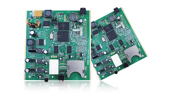
鑫景福致力于满足“快速服务,零缺陷,辅助研发”PCBA订购单需求。


In order to improve and ensure the high quality welding of PCB circuit and prevent false soldering and false soldering, correct operation and use of electrIC soldering iron and reasonable selection of soldering tin and flux are key points, while the treatment of lead pins of PCB components to be soldered, appropriate temperature of tin on PCB and flexible replacement of wattage and power of electric soldering iron are also key points. Generally speaking, in the welding process of electronic circuits, the following specific points and measures can be summarized to ensure the welding quality.
Flexible control of wattage and power of electric soldering iron:
In electronic circuit welding, electric soldering irons are special welding tools. At present, the power of various types of internally heated and externally heated electric soldering irons is different. In the actual application welding process, when the power is too SMAll, the welding temperature is too low, false soldering and false soldering between components and circuits are easy to occur, while when the power is too large, the welding temperature is too high, which also extremely causes the wiring on the Circuit PCB board and components to be damaged due to overheating, And the problem that the iron head is easy to be oxidized and burned. Therefore, generally speaking, small power, internally heated electric soldering irons of about 20w, 25w and 40w are often used in electronic circuits. At the same time, the tip of the soldering iron is in a slope shape, which is suitable for component points with a slightly larger distance between welding points, and the tip of the soldering iron will not be frequently oxidized and ablated. For components with a relatively narrow line spacing between welding points, such as integrated modules and arrayed microswitches, it is suitable and flexible to use a pointed tip.
2. Self transformation and renovation of electric soldering iron head:
In the daily line welding, sometiMES we slightly modify the existing soldering head or process the old soldering head, which makes it more practical and convenient to use and reuse the old soldering head.
1、 Saw off the slope plane of the original internal heated soldering iron head with a hacksaw, and then use a file to smooth the soldering iron head into a flat shape, and then use a left 1.5mm drill bit to drill a small hole with a depth of about 2mm in the center of the plane. In this way, the modified soldering iron head is not only easy to tin, but also convenient to remove the component pin, and the welding point of its welding point is free of burrs and bright and smooth.
2、 Reuse and processing of waste soldering iron head. For the internally heated soldering iron head that has been ablated, we will add a section of brass rod with the same diameter at the residual head of the front end (the brass rod can be welded with the soldering iron head with an oxygen gas welding tool), and then grind the welding scar on the grinder to round, and finally grind the brass rod head to a sloping surface. It has been proved in practice that the brass tip is easier to tin than the original copper tip, and is more resistant to oxidation and ablation in use, thus effectively prolonging the reuse life of the tip to a large extent.
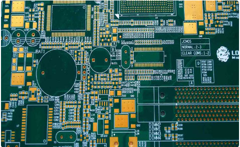
Circuit welding
3. Cleaning and decontamination of PCB and components before PCB welding:
In some failures that produce false solder joints, some components should also be desoldered, and some circuit boards should also be desoldered, which is due to the failure to do a good job of cleaning and decontamination before welding. There is a layer of oxide on the copper foil solder joint mounting surface of the printed circuit board, and when the copper foil solder joint that has been soldered and disassembLED for several times has accumulated oil dirt, once it is not cleaned, it is urgent to tin the welding elements, which will easily lead to the fault of false soldering. Therefore, the printed circuit board should be wiped with alcohol before tin, and the residual oil dirt should be scraped with a knife or sandpaper. The important point to grasp in the specific welding is that the soldering iron head should be circled around the root of the element lead leg, and moved away from the soldering iron after staying for a moment, so that the welded spot is round, burr free and bright.
At the same time, attention should be paid to various lead pins. Before welding, they should be polished and decontaminated with diamond fine sandpaper, plated with a little tin, and then inserted into the printed board for welding. This is a quite necessary operation link. Of course, the lead pins of some electronIC components have been tinned when they leave the factory, but because of the storage time, the surface of the lead pins of components is easy to produce oxide layer, so it is better to decontaminate and tin again before welding, so as to ensure the absolute reliability of welding quality.
When welding some thin wire wrapped leads, enamelled wire leads, yarn wrapped wire leads, etc., if we use the scraping method for the insulation paint layer of the leads, it is easy to cut off the thin wires or damage the leads. For this reason, we can lay the thin lead wire to be welded flat on a glass plate, and then touch the soldering iron head with a little rosin, which can be pressed on the wire head and dragged back and forth. Due to the effect of heat and rosin, the insulation layer of the wire head is quickly wiped off and tin can be quickly applied. When welding the lead wires of multi strand wrapped yarn, it is often necessary to polish the yarn layer wrapped outside the wire with fine sandpaper before tin coating. However, the wire is easy to be broken when the diameter of the wrapped yarn is very fine. The best way is to put the yarn wrapped thread head on the lighter and burn it quickly, then put it on the glass plate and drag the tin onto the thread head with the soldering iron head DIPped in rosin, so that the multi strand thread head can be continuously twisted and the tin can be evenly and cleanly coated.
4. Characteristics and selection of solder wire and flux:
At present, the special soldering tin for electronic circuits is a kind of hollow tubular solder wire, which contains rosin and active substances in the hollow tube cavity of the wire. It can ensure sufficient mechanical strength and reliable conductivity after the solidification of the solder joint. The diameter of rosin solder wire is also large, generally 0.5, 0.8, 1.2, 1.5, 2.0, 2.5, 3.0 mm and other specifications and models. The selection can be determined according to the size of the actual solder joint and the welding area. When welding common electronic components, it is appropriate to choose a solder wire with a diameter of about 1.2 mm, of course, it can be flexibly selected in actual use. Other hardware solder bars and solder blocks should not be used in electronic circuit welding to ensure the absolute reliability of solder quality because of too many impurities.
The function of flux is to prevent the metal surface (spot) of PCB component from being welded under high temperature due to the oxidation at the joint. The commonly used types of flux include rosin, rosin perfume, solder paste, solder oil, etc. In the use of PCB circuit welding, try to avoid the use of corrosive acid and alkali fluxes such as solder paste. Although sometimes solder paste welding can reduce false soldering, the problem of corrosive components and PCB will occur over time.


抖音二维码

Q Q二维码

微信二维码
点击
然后
联系
然后
联系
电话热线
13410863085Q Q

微信

- 邮箱