main requirements for PCB characteristic impedance control
PCB single-sided circuit board design needs to contact a lot of professional data and some physICal knowLEDge, which can be said to be a comprehensive technical project. To make high-quality PCB, you need not only a solid foundation, but also sensitivity to impedance. The impedance involved in PCB mainly includes the following aspects:
When DC current of printed pcb circuit board passes through the wire, it will suffer a resistance, which is called resistance. The resistance is R, and the numerical unit is "ohm" (Ω).
The relationship between resistance and current and voltage is: R=V/I
In addition, the resistance is also related to the resistivity of the conductor material( β), The length (L) of the conductor is related to the cross-sectional area (S) of the conductor. R= β L/S
1. Resistance
When the AC current flows through a conductor, the resistance it receives is called Impedance, which is Z in Ω.
At this time, the resistance is different from the resistance encountered by DC current. In addition to the resistance of resistance, there are also resistance problems of inductive reactance (XL) and capacitive reactance (XC).
To distinguish DC resistance, the resistance encountered by AC is called impedance (Z).
Z=√ R2 +(XL -XC)2
2. Impedance (Z)
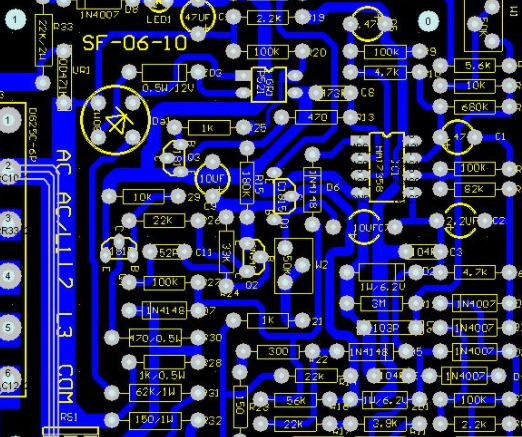
In recent years, with the improvement and application of IC integration, its signal transmission frequency and speed are getting higher and higher. As a result, when the signal transmission (transmission) reaches a certain value in the PCB wire, it will be affected by the PCB wire itself, resulting in serious distortion or complete loss of the transmission signal. This shows that the "thing" that PCB wire "flows" is not current, but the transmission of square wave signal or pulse in energy.
3. Characteristic impedance control (Z0)
The resistance to transmission of such "signal" is also called "characteristic impedance", and the symbol is Z0.
Therefore, it is not enough to solve the problems of "on", "off" and "short circuit" on PCB wires, but also to control the characteristic impedance of the wires. In other words, the quality of transmission lines for high-speed transmission and high-frequency signal transmission is much stricter than that of transmission lines. It can be accepted when the "open circuit/short circuit" test is no longer passed, or the notch and burr do not exceed 20% of the line width. The characteristic impedance value must be measured, and this impedance must also be controlled within the tolerance, otherwise, only scrap is allowed, and rework is not allowed.
At present, the required control range of the characteristic impedance Z0 of the multilayer board signal transmission line is usually 50 Ω± 10%, 75 Ω± 10%, or 28 Ω± 10%.
Four factors must be considered for the controlled range of change:
(1) Signal line width W;
(2) Signal wire thickness T;
(3) Thickness of medium layer H;
(4) Dielectric constant ε r 。
The influence of most is the thickness of the medium, followed by the dielectric constant, wire width, and the influence of most is the thickness of the wire. After selecting the substrate, ε The change of r is very SMAll, and the change of H is also small. T is easy to control, but it is difficult to control the line width W at ± 10%, and the line width problems include pinholes, notches, and dents on the wire. In a sense, the most effective way to control Z0 is to control and adjust the linewidth.
Mastering the data of these physical properties will be very helpful for PCB design. Experienced technicians will consider all aspects of factors to avoid quality problems after most. This is not only based on experience, but also a full understanding of physical properties.
然后
联系
电话热线
13410863085Q Q

微信

- 邮箱


