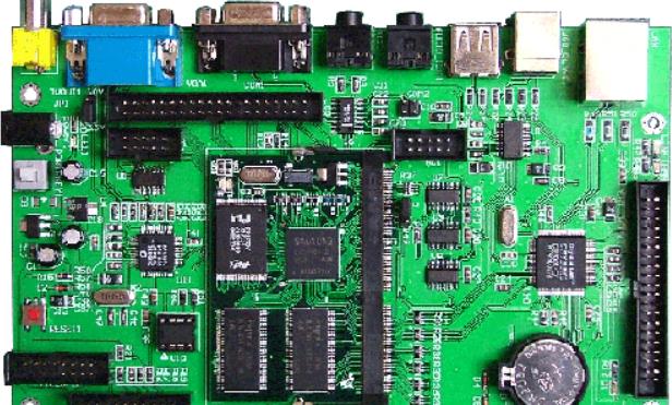
SMT lead-free solder meets the requirements for one-time use
surface mount uses lead-free solder to meet the first condition
"Lead" is a compound, whICh not only pollutes water sources, but also pollutes and destroys soil and air. Once the environment is polluted by lead, its treatment cycle and funds are very huge, but the harm to the human body is greater. This problem is also getting more and more attention. With the enhancement of people's environmental awareness, the use of lead in various industries has become more and more cautious. Among them, in SMT chip processing, customers from different industries will be asked whether there are lead-free requirements for the welding process, which means that the electronic manufacturing industry has very strict requirements for lead-free assembly process.
First of all, when using lead-free solder in SMT wafer processing, it must be able to truly meet the environmental requirements. Lead should not be removed blindly, but new toxic or harmful substances should be added; In order to ensure the solderability and reliability of lead-free solder, and to consider the cost borne by customers and other issues. In general, lead-free solder in smt chip processing should meet the following requirements as far as possible:
First, the melting point of lead-free solder for welding should be treated with SMT chip at a very low temperature, as close as possible to the eutectic temperature of 63/37 tin lead alloy, 183 ℃
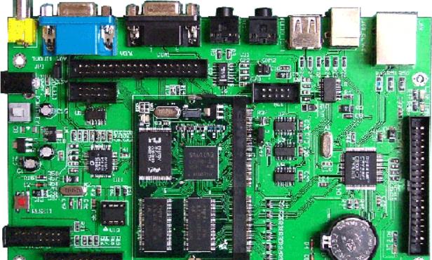
Circuit board
If the eutectic temperature of the new product is only a few degrees higher than 183 ℃, this should not be a big problem, but there is no such lead-free solder that can really promote and meet the requirements of the welding process; In addition, before developing lead-free solders with lower eutectic temperatures, it is necessary to reduce the temperature difference between melting intervals of lead-free solders, which means minimizing the temperature range between its solidus and liquidus The minimum solidus temperature is 150 ℃, and liquidus temperature depends on the specific application (Tin bar for wave soldering: below 265 degree Celsius; tin wire: below 375 degree Celsius; Solder paste for surface mounting: below 250 degrees Celsius, usually the reflow temperature should be lower than 225 to 230 degree Celsius)
Second, lead-free solders used for smt wafer processing must have good wettability; Under normal conditions, lead-free solder is kept above the liquidus for 30 to 90 seconds during reflow soldering. The contact time between the solder pin of tin wave soldering and the surface of the circuit board substrate is about 4 seconds. After using lead-free solder, ensure that the solder has good wetting efficiency within the above time range to ensure high-quality welding effect.
Main causes of surface mounting machine throwing
Countermeasures: Clean and replace the nozzle; Cause 2: The identification system may be damaged due to problems in the identification system, poor vision, unclean vision or laser lens, debris interference identification, improper selection of identification light source, insufficient intensity and gray scale. Countermeasures: Clean and wipe the surface of the identification system, keep it clean and free of debris, adjust the intensity and gray scale of the light source, and replace the identification system components; Cause 3: Position problem, the recovered data is not in the center of the data, and the recovery height is incorrect (usually press 0.05MM as the standard after contacting the parts), resulting in misplacement, incorrect picking, offset, and the identification does not match the corresponding data parameters, which is considered invalid by the identification system and discarded.
Countermeasures: Clean and replace the nozzle;
Cause 2: The recognition system may be damaged due to problems in the recognition system, poor vision, dirty vision or laser lens, debris interference recognition, improper selection of recognition light source, insufficient intensity and gray scale.
Countermeasures: Clean and wipe the surface of the identification system, keep it clean and free of debris, adjust the intensity and gray scale of the light source, and replace the identification system components;
Cause 3: The position problem, the reclaiming is not in the data center, and the reclaiming height is incorrect (usually press down 0.05MM after contacting the parts), resulting in deviation. The reclaiming is incorrect, and there is deviation, and the identification shall be followed. The data parameters do not match, and the identified system discards them as invalid data.
Countermeasures: Adjust the reclaiming position;
Cause 4: Vacuum problem, insufficient air pressure, blocked vacuum pipe channel, blocked vacuum channel by guide material, or vacuum leakage due to insufficient air pressure, which makes it impossible to retrieve information, or it falls on the road after picking up.
Countermeasures: sharply adjust the air pressure to the air pressure required by the equipment (such as 0.5~0.6Mpa -- YAMAHA mounter), clean the air pressure pipeline, and repair the air leakage channel;
Cause 5: Program problem. The component parameters in the editor are not set correctly, and they do not match the actual size, brightness and other parameters of the incoming material, which will cause the identification to fail and be discarded.
Countermeasures: Modify component parameters and search for the best parameter settings of components;
Cause 6: Nonconforming products such as incoming material problems, non-standard incoming materials, pin oxidation, etc.
Countermeasures: IQC will check the incoming materials and contact the SMT supplier;
Cause 7: Feeder problem, feeder position deformation, feeder feeder is serious (feeder ratchet wheel is damaged, material belt hole is not stuck on the feeder ratchet wheel, there are foreign matters under the feeder, spring aging or power failure), resulting in insufficient or poor material recovery and throwing, and damaging the feeder.
Countermeasures: Adjust the feeder, clean the feeder platform, and replace damaged parts or feeder
The above is the explanation given by the editor of PCB circuit board company.
If you want to know more about PCBA, you can go to our company's home page to learn about it.
In addition, our company also sells various circuit boards,
High Frequency Circuit Board and SMT chip are waiting for your presence again.
然后
联系
电话热线
13410863085Q Q

微信

- 邮箱


