鑫景福致力于满足“快速服务,零缺陷,辅助研发”PCBA订购单需求。
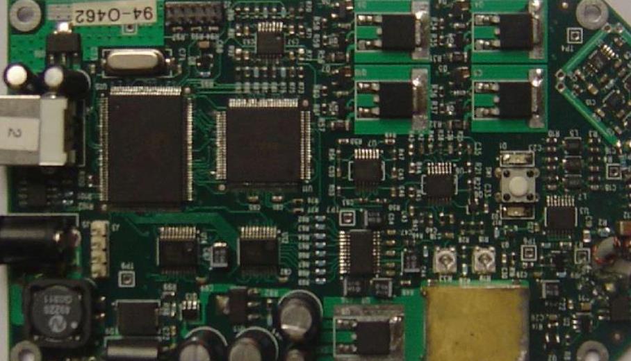
What are the printing techniques of SMT solder paste?
The process flow of using printing solder paste SMT chip processing is: preparation before printing, adjustment of the working parameters of the printing machine, printing solder paste, printing quality inspection, cleaning and finishing
The steps and description of this process are as follows:
(1) Preparation before printing.
The first thing to check is the printing working voltage and air pressure; Understand the process requirements of products; Browse the PCB product certifICate. If the PCB manufacturing date exceeds 6 months, the PCB should be dried at 125 ℃/4 hours, usually the day before; Check whether the manufacturing date of solder paste is within 6 months, whether the brand specification meets the current Production requirements, and whether the viscosity of stencil printing solder paste is 900-1400Pa s It is better to be 900Pa s. After taking it out of the freezer, it should be recovered at room temperature for at least 2 hours, and fully stirred for future use. The newly activated solder paste should be MARKed with the opening date and user name on the tank cover; Check whether the template is consistent with the PCB currently produced, whether the window is blocked, and whether the appearance is clean
After turning on the power and air supply, the printing machine will enter the open state (initialization). For newly produced pcb, you must first input the relevant parameters of the length, width, thickness and location identification mark of the PCB. Mark can correct processing errors on PCB. When making the mark image, the image is clear, the edge is smooth, and the contrast is strong. At the same time, various working parameters of the printing machine should be input, including printing stroke, scraper pressure, scraper running speed, PCB board height, and related parameters such as number of templates, separation speed, template cleaning time and method.
After setting the relevant parameters, you can put them into the template. Transfer the PCB to the working platform of the printing machine to keep the position of the template window and the position of the PCB grounding pattern within a certain range (the machine can automatically recognize). When the thickness of PCB is less than 0.5mm, the side fixing method is used. This will cause PCB board deformation. In this case, vacuum adsorption can be used to position the back of PCB. The corresponding printing machine workbench shall be equipped with positioning support plate for adsorbing pcb circuit board.
Install the scraper and run it in. At this time, the PCB and the template should generally maintain a "zero distance". Carry out trial printing on the first PCB to check the printing effect, further adjust the position relationship between the PCB and the template in X, F, Z and formula, achieve accurate alignment between the template window and the PCB grounding pattern, and adjust the relevant parameters of the device again to achieve the best printing effect. After full adjustment, save relevant parameters and PCB code. After that, you can place enough solder paste for official printing.
The above operation sequence of different machines is different. Machines with high degree of automation are easy to operate and can succeed at one time.
(3) Print solder paste.
Pay special attention to the following matters when printing solder paste: the amount of solder paste used for the first time should not be too much, and it is generally estimated according to the size of PCB. The reference quantity is as follows: about 200g in A5 format; B5 format is about 300g; A4 format is about 350g. During use, special attention should be paid to adding new solder paste to ensure that the solder paste can roll forward during printing. Pay special attention to the environmental quality when printing solder paste: no wind, clean, temperature (23 ± 3) ℃, relative humidity<70%.
(4) Printing quality inspection.
For the inspection of screen printing quality, the methods used in this stage mainly include visual inspection and two-dimensional/three-dimensional inspection. When checking the printing quality of solder paste, different inspection tools and methods should be used according to the type of parts, and visual methods (using a magnifying glass) should be used. It is applicable to the case where there are no fine pitch QFP components or SMAll batch production, and its operating cost is low. However, the reliability of echo data is low and easy to be missed. When printing complex printed circuit boards (such as computer motherboards), visual inspection is the best, while online testing is the best. The reliability is 100%. It can not only monitor, but also collect real data required for process control.
The principle of inspection standard is: when there is a fine spacing QFP (0.5mm), a comprehensive inspection shall be generally carried out; When there is no fine pitch QFP, random inspection can be carried out.
Inspection standard: according to the enterprise standard or ST10670199 and IPC standard formulated by the company.
Disposal of nonconforming products: When printing quality problems are found, stop the machine for inspection, analyze the causes, and take measures to improve. Unqualified QFP pads shall be cleaned with absolute alcohol and printed again.
(5) Clean up and finish.
When the SMT product is completed or the working day ends, the sample and scraper must be cleaned If the window is blocked, do not scratch or poke it with a hard metal needle to avoid damaging the shape of the window Solder pastes are stored in another container and can be reused according to the situation After cleaning the sample, blow it with compressed air and store it on the tool shelf The scraper should also be placed at the designated position, and the scraper head should not be damaged At the same time, let the machine return to the shutdown state, turn off the power and air supply, fill in the work record form, and maintain the machine
The process flow of using printing solder paste SMT chip processing is: preparation before printing, adjustment of the working parameters of the printing machine, printing solder paste, printing quality inspection, cleaning and finishing
The steps and description of this process are as follows:
(1) Preparation before printing.
The first thing to check is the printing working voltage and air pressure; Understand the process requirements of products; Browse the PCB product certifICate. If the PCB manufacturing date exceeds 6 months, the PCB should be dried at 125 ℃/4 hours, usually the day before; Check whether the manufacturing date of solder paste is within 6 months, whether the brand specification meets the current Production requirements, and whether the viscosity of stencil printing solder paste is 900-1400Pa s It is better to be 900Pa s. After taking it out of the freezer, it should be recovered at room temperature for at least 2 hours, and fully stirred for future use. The newly activated solder paste should be MARKed with the opening date and user name on the tank cover; Check whether the template is consistent with the PCB currently produced, whether the window is blocked, and whether the appearance is clean
After turning on the power and air supply, the printing machine will enter the open state (initialization). For newly produced pcb, you must first input the relevant parameters of the length, width, thickness and location identification mark of the PCB. Mark can correct processing errors on PCB. When making the mark image, the image is clear, the edge is smooth, and the contrast is strong. At the same time, various working parameters of the printing machine should be input, including printing stroke, scraper pressure, scraper running speed, PCB board height, and related parameters such as number of templates, separation speed, template cleaning time and method.
After setting the relevant parameters, you can put them into the template. Transfer the PCB to the working platform of the printing machine to keep the position of the template window and the position of the PCB grounding pattern within a certain range (the machine can automatically recognize). When the thickness of PCB is less than 0.5mm, the side fixing method is used. This will cause PCB board deformation. In this case, vacuum adsorption can be used to position the back of PCB. The corresponding printing machine workbench shall be equipped with positioning support plate for adsorbing pcb circuit board.
Install the scraper and run it in. At this time, the PCB and the template should generally maintain a "zero distance". Carry out trial printing on the first PCB to check the printing effect, further adjust the position relationship between the PCB and the template in X, F, Z and formula, achieve accurate alignment between the template window and the PCB grounding pattern, and adjust the relevant parameters of the device again to achieve the best printing effect. After full adjustment, save relevant parameters and PCB code. After that, you can place enough solder paste for official printing.
The above operation sequence of different machines is different. Machines with high degree of automation are easy to operate and can succeed at one time.
(3) Print solder paste.
Pay special attention to the following matters when printing solder paste: the amount of solder paste used for the first time should not be too much, and it is generally estimated according to the size of PCB. The reference quantity is as follows: about 200g in A5 format; B5 format is about 300g; A4 format is about 350g. During use, special attention should be paid to adding new solder paste to ensure that the solder paste can roll forward during printing. Pay special attention to the environmental quality when printing solder paste: no wind, clean, temperature (23 ± 3) ℃, relative humidity<70%.
(4) Printing quality inspection.
For the inspection of screen printing quality, the methods used in this stage mainly include visual inspection and two-dimensional/three-dimensional inspection. When checking the printing quality of solder paste, different inspection tools and methods should be used according to the type of parts, and visual methods (using a magnifying glass) should be used. It is applicable to the case where there are no fine pitch QFP components or SMAll batch production, and its operating cost is low. However, the reliability of echo data is low and easy to be missed. When printing complex printed circuit boards (such as computer motherboards), visual inspection is the best, while online testing is the best. The reliability is 100%. It can not only monitor, but also collect real data required for process control.
The principle of inspection standard is: when there is a fine spacing QFP (0.5mm), a comprehensive inspection shall be generally carried out; When there is no fine pitch QFP, random inspection can be carried out.
Inspection standard: according to the enterprise standard or ST10670199 and IPC standard formulated by the company.
Disposal of nonconforming products: When printing quality problems are found, stop the machine for inspection, analyze the causes, and take measures to improve. Unqualified QFP pads shall be cleaned with absolute alcohol and printed again.
(5) Clean up and finish.
When the SMT product is completed or the working day ends, the sample and scraper must be cleaned If the window is blocked, do not scratch or poke it with a hard metal needle to avoid damaging the shape of the window Solder pastes are stored in another container and can be reused according to the situation After cleaning the sample, blow it with compressed air and store it on the tool shelf The scraper should also be placed at the designated position, and the scraper head should not be damaged At the same time, let the machine return to the shutdown state, turn off the power and air supply, fill in the work record form, and maintain the machine
点击
然后
联系
然后
联系
电话热线
13410863085Q Q

微信

- 邮箱


