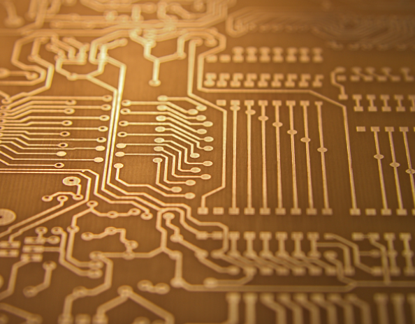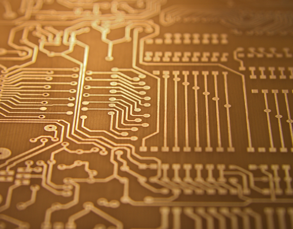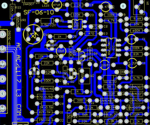
Main three-stage heat source of PCB
There are 3 main heat source PCB circuit boards in the room:
(1) Heating of electronIC components;
(2) Heating of PCB itself;
(3) Heat from other parts.
Among the three heat sources, the heating value of electronIC components is the highest, which is the main heat source, followed by the heat generated by PCB. The external heat depends on the overall thermal design of the system, which is not considered temporarily. Then the purpose of thermal design is to select appropriate measures and methods to greatly reduce the temperature of electronic components and PCB, so that the system can work normally at the appropriate temperature.
The following aspects can be considered:
1. Heat the PCB itself through the main pipe At present, PCB circuit board materials are widely used, such as epoxy glass cloth or phenolic resin glass cloth. In addition, a SMAll amount of paper based copper clad laminate is also used Although this kind of substrate has excellent power efficiency, processing efficiency and poor heat dissipation As the heat dissipation path of high thermal electronic components, it is basically impossible to expect the heat from the PCB itself, but from the surface of the electronic components Radiate heat to the surrounding air
Circuit board

However, as time goes by, smart electronic products have entered the era of miniaturization of components, high-density installation and high heating assembly. It is not enough to rely solely on the surface heat dissipation of electronic components with small surface area. At the same time, due to the large selection of surface mounted electronic components (such as QFP and BGA), a large amount of heat generated by electronic components is transferred to PCB. In this case, the most suitable heat dissipation pipe is the newly added pcb circuit board which is in direct contact with the heating electronic components. Its own heat dissipation capability is conducted or transmitted through PCB.
2. High heating electronic components plus heat sink and heat conduction plate. When a small number of electronic components in a PCB have a large calorific value (less than 3), a radiator or heat pipe can be added to the heating electronic components. When the temperature cannot be reduced, the fan can be selected. The radiator enhances the cooling effect. When the heating capacity of electronic components is large (more than 3), large heat dissipation covers (plates) can be used. It is a highly customized special radiator based on the position of the heating electronic components on the PCB circuit board, or different electronic components are cut on the large flat panel radiator.
The heat dissipation cover is buckLED on the surface of the electronic components as a whole to contact each electronic component for heat dissipation. However, due to the poor consistency of electronic components during assembly and welding, the heat dissipation effect is not very good. Generally speaking, soft thermal phase change heat pad is added on the surface of electronic components to improve the heat dissipation effect.
3. Select appropriate cabling design to achieve heat dissipation. Due to the poor thermal conductivity of the resin in the board, the copper foil wire and hole are good heat conductors. The residual rate of the newly added copper foil and the newly added heat conduction hole are the main means of heat dissipation.
4. When connecting high heat dissipation electronic components to the substrate, the thermal resistance between them should be minimized. In order to better meet the requirements of thermal characteristics, some thermal conductivity materials (such as a layer of thermal conductive silicone glue) can be used on the bottom of the chip, and a certain contact area should be maintained so that electronic components can dissipate heat.
5. In the horizontal direction, high-power devices are arranged as close to the edge of the printed circuit board as possible to shorten the heat transfer path; In the vertical direction, high-power devices are arranged as close to the top of the printed circuit board as possible, which can reduce the work of such electronic components. The effect of time on the temperature of other electronic components.
6. The heat dissipation of the printed board in the equipment mainly depends on the air flow. The air flow path shall be studied during the design, and the devices or printed boards shall be reasonably configured. When the air flows, it always tends to flow in the place with low resistance. When the equipment is installed on the printed circuit board, avoid leaving large space in specific areas. The same problem should also be paid attention to when multiple printed circuit boards are included in the whole machine.
7. The equipment that is more sensitive to temperature should be placed in the lowest temperature area (such as the bottom of the equipment). Do not place it directly above the heating device. It is better to stagger multiple devices on a horizontal plane.
8. Avoid hot spot concentration on PCB, distribute power supply evenly on PCB as far as possible, and keep PCB surface temperature efficiency consistent and consistent In the design process, it is usually difficult to achieve strict uniform distribution, but areas with high power density must be avoided to prevent hot spots from affecting the normal operation of the entire circuit
然后
联系
电话热线
13410863085Q Q

微信

- 邮箱


