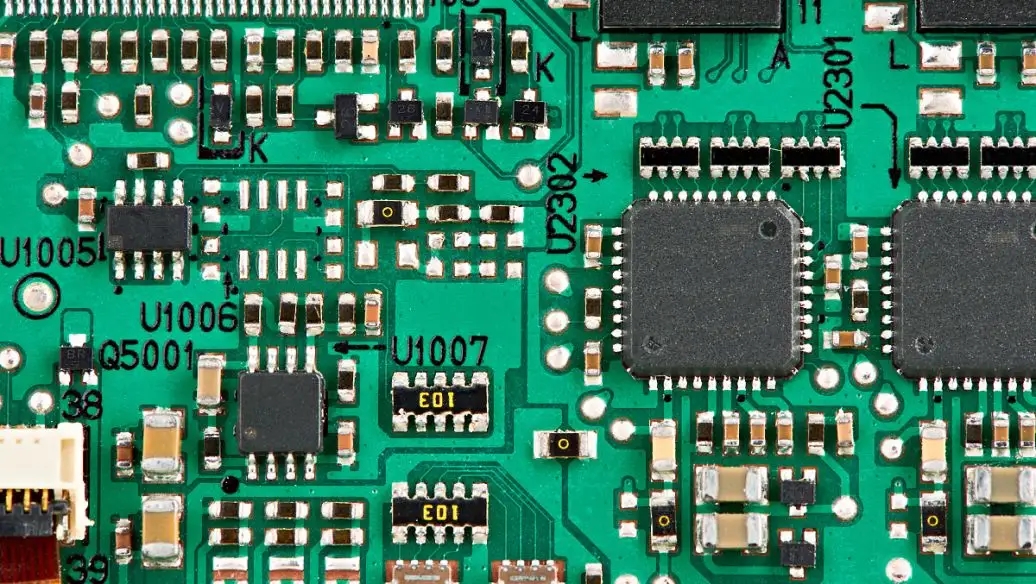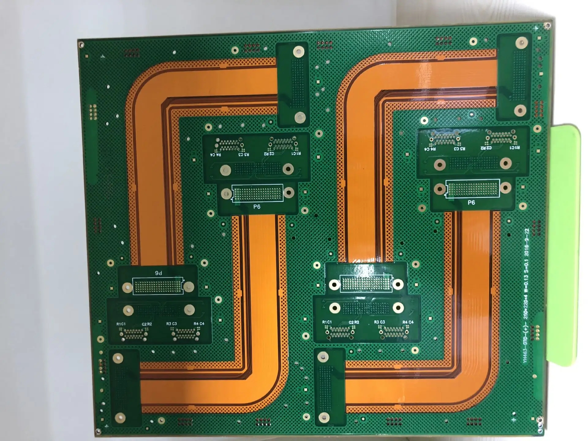
DetaiLED explanation of BGA components and their repair process
1 BGA removal operation
a. Place the BGA PCB with abnormal appearance in the maintenance station
b. After aligning the BGA, start the upper and lower heaters at the same time. When the temperature of the lower plate is about 100 ℃, move the upper heating cover directly above the BGA, and pull it out when the melting point temperature is reached
2. BGA solder ball removal
Use SIMple tin absorbing wire to remove residual tin balls and tin slag on BGA PAD and PCB
Operation assistance: a SMAll amount of liquid FLUX is added to the surface of the tin absorption line, while the BGA surface is also coated with liquid FLUX, and then the soldering iron is used to heat the tin absorption line in a radial way. The flat type soldering iron is preferred. Because of the large heating area, and the relatively wide heat absorption of the tin absorption line, it is easier to reach the tin melting temperature, so you can drive gently to remove tin. The soldering iron should not use a sharp tip, because the sharp tip is easier to pierce the tin absorption line, when heating the sliding tin absorption line, you can directly scratch the PAD on the BGA surface, The BGA PAD is easy to be damaged, whICh may cause the PAD to peel off, or the surface of the tin absorption line to be damaged, which may cause an irregular switch. The PAD will also be damaged. When the soldering iron head is heated on the surface of the tin absorption line, the pressure is prohibited. The tin absorption line itself reaches the tin melting temperature, which will naturally absorb the PAD tin slag. The speed should be controlled appropriately, and it should not stay too long.
3. PCB and BGA solder balls shall be cleaned by solvent
After the tin removal operation is completed, the residual FLUX on the BGA and PCB after tin removal and heating has changed chEMIcally and deteriorated, which not only has no soldering effect, but will cause film isolation and solder rejection. If no solvent cleaning process is used, even if a new FLUX is added, covering the deteriorated FLUX will not help the soldering effect. It is a process ignored by general maintenance operations. Cleaning the residual FLUX on the BGA depends on the important and necessary previous operations in the soldering effect of the solder ball, The selection of FLUX also depends on the welding effect. The requirements and necessary steps of FLUX are the conditions of maintenance yield.
4. BGA drying process
After solvent cleaning, BGA will inevitably cause moisture intrusion. Generally, BGA IC structures have PCB materials and ceramic materials, and PCB structures are more vulnerable to moisture intrusion. Once PCB contains moisture, the integrity of BGA body structure may be damaged in any step involving high-temperature operations. At present, PCB structure BGA accounts for 90%, and ceramic BGA accounts for 10%. PCB structures are mostly used. Although the drying process is inconSPIcuous in small details, if it contains moisture, serious damage will be caused, Do not ignore the necessity of this operation because it causes BGA PCB to separate from the wafer and PCB to burst.

5. BGA rosin paste printing
In the previous operation of ball planting, FLUX was printed at each PAD point of BGA by printing. The printing range of PAD points was reduced by about 75%. The optimum thickness of FLUX printed steel plate was T=0.10mm~0.12mm. A small hand printing table was provided for BGA FLUX printing operation. BGA IC fixed bottom mold design. FLUX printing BGA at BGA PAD point was the correct maintenance method, with a success rate of 95%~99%, which may cause 1%~5% chance of defects. Two points are summarized:
(1) The BGA PAD point is not really flat, and there are hilly residues. When the tin ball is placed with a sloping PAD point, it is found that the ball moves along the hilly slope direction after about 30 seconds of placing the tin ball, resulting in ball holding rate.
(2) The printing operation was poor, and the error occurred. The PAD point was not printed with FLUX, which caused the solder ball to be unavailable for soldering, resulting in dry soldering, the solder ball fell off when it was pulled, or it was not firm. The above two points were caused by a 5% chance of poor performance. Pay attention to the negligence of the operation and the PAD point removal. It was not difficult to achieve a yield of 100%.
Incorrect mode of FLUX printing operation: the following undesirable conditions are likely to occur
(1) The probability of holding the ball can reach 20%~30%.
(2) The quantity of FLUX is not easy to control, but too much. During BGA's solder ball reflow process, the FLUX is hot after reflow, and the FLUX is boiling, forcing the solder ball to roll. It is normal to hold the ball in many places
(3) It is easy to paint and print. The corners are not really painted and printed on FLUX. PAD points are lack of FLUX soldering. The solder balls are dry soldered and not firmly soldered. The solder balls fall off when you move them. The maintenance quality of this operation is only to increase the chances of repair. BGA is not allowed under the condition that it is required to strive for successful repair once.
6. BGA solder ball implantation
The tin ball is used to enter the machine for fully automatic ball planting, which is fast, reliable and easy to operate. The tin ball mold and BGA mold can be matched with the replacement demand of SIZE, which can be used for operations of different specifications. It has high mobility and versatility. There is no brand limit or PIN number limit. It meets the requirements of BGA for introducing different SIZEs with each passing day. The whole ball planting process is automatic. In particular, it is prohibited to place the ball by hand or fill the ball. The oxidation damage of alkaline moisture in the hand is far more serious than the natural contact of air, Tooling fixture ball filling is easy to damage or deform the appearance of the solder ball. The hardness of the tin is low, and it is easy to deform due to a slight external force. The use of the solder ball implanter is a better way for BGA ball planting.
7. BGA solder ball reflow operation
Solder ball implanter. After the ball planting is completed, take an empty board of the main machine, and at the same time, accumulate multiple BGA balls. Use the production line REFLOW to directly conduct solder ball reflow operations, and quickly reflow multiple BGAs at the same time. The correct maintenance process can achieve a yield of 99%. Only 1% of people are negligent in the operation. A little attention can also be avoided. Pay attention to the details of the procedure. It is not difficult to repair BGA, and the success rate is handy.
8. BGA reconstruction
When the solder ball is welded with the BGA PAD and a complete BGA is created, it is also the goal of maintenance. If you have a complete BGA, you can say that 90% of the maintenance work has been completed
9. BGA soldering back to PCB
The BGA special disassembly and assembly equipment is used to place the BGA parts in the PCB reflow position, and the BGA is soldered back to the PCB bGA position. This procedure is the last station of the whole maintenance. Each station is the key to success in maintenance. Experience, proficiency, and good use of maintenance equipment are important prerequisites in guided maintenance.
A. Turn on the left switch of IR500 first
B. Set the power of upper and lower heating zones (lower 8, upper 7-9)
C. Place PCB on fixture platform
D. Move the PCB to the non heating area and coat the flux on the solder ball of PCB BGA PAD and BGA parts
E. After aligning the BGA part with PCB, move it to the heating area
F. Align BGA center position on PCB with laser spot
G. Place the temperature sensing rod near the BGA to be reworked
H. When the temperature shows about 80 ° C, move the upper heater directly above the BGA (the lower heater shall be fully preheated to avoid bending)
1. After the temperature is displayed to about 170-180, remove the upper heater and complete the reflow operation (note whether the BGA solder ball is melted, and it will take about 10 seconds after the distance between BGA and PCB is reduced)
J. The heating temperature and time shall be paid attention to when the size of each BGA is different to avoid damage to BGA caused by too high temperature and too long time.
然后
联系
电话热线
13410863085Q Q

微信

- 邮箱


